 +91 9824067241 | +91-79-400-33-800, 4800 4801
  Hire@ScaffoldingOnHire.com
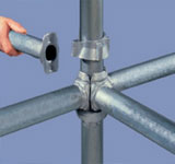

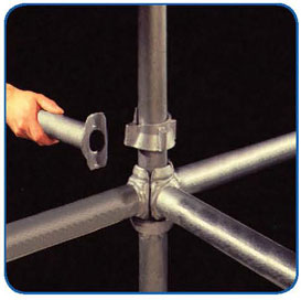
1. Locate the blade and of ledgers and transoms into cup.
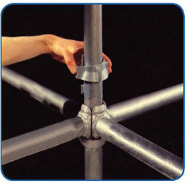
2. Slide the upper cup down the standard and rotate.
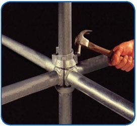
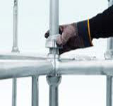
3. Tighten with a hammer blow.
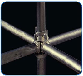
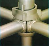
4. A positive and rigid connection of up to four units is achieved in one single actions.
Cuplok galvanized scaffold system. it is a well –proven heavy –duty support system. yet one which is relatively light and easy to assemble .it is as multi- purpose system, suitable not only for false work support but access as well, and is particularly suitable for building and civil engineering projects like motorway bridge as well as office and retail developments.
Technical Data : Loading Capacity
(Bracina omitted for claritv)
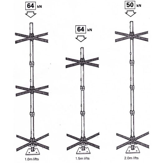
Notes :- Design Factors
The capacity of cuplok is based on 1.8m and less horizontal lengths. if 2.5m horizontals are used, the loadings will be:
1.5m lifts 60kn
2.0 lifts 45kn
The Loading capacities shown are based on internal verticals restrained in all four direction. For external verticals restrains in either two or three the safe working loads may be reduced by up to 20%.
The Loading Diagram is based on eccentric loads of up to 25mm and fully extended base head jaks in a ‘worst case’ situation.
If jack extensions are below 35mm and standard eccentricities do not excedd 5mm,loads can be increased to 74Kn.
The information shown above only applies to high grade Cuplok, Which is identified by 4 Lugs on the Top Cups. if 3-Lug Cuplok Verticals are introduced into the structure a reduced capacity applies as follows.
The permissible le loads on verticals and jacks in cuplok false work structure are based on suitably braced structures in accordance with HKL’S Design recommendations.